Frequency Counter
Project completed in 2006-12-30
During the Winter break my dentist convinced me that I needed to have my 2nd wisdom teeth removed. Having done this previously without much pain, I thought it would be a good idea. It turned out to be much more involved and I was out of commission for 2 weeks which was no fun at all. I was in bed most of the time, but one day I made myself get out of the house to buy the temperature controlled soldering iron that I've always wanted. I needed an excuse to use the soldering iron so I figured that I might as well as make a frequency counter which is something that I've always wanted, but lacked in my lab.
Description
Having used frequency counters before, I thought it would be a good idea to incorporate some of my favourite features. These include:
- Frequency counter and counter mode
- Overflow indicator
- Data hold
- Flexible time base
- 6 digit resolution
- No leading zeros in the display
- Minimum fmax of around 5 MHz (my signal generator only goes up to 3 MHz)
- TTL / CMOS input (most signal generators have a TTL output used for triggering, etc)
I also bought a few tubes of 7 segment LEDs and 74ALS373 in the recent past. Why not put them into good use?
Design
Here's the schematic. I drew it up in OrCAD PSpice a while back. Since then, I have lost the design files, but fortunately, I kept a hard copy, complete with annotations of the colour of the wire that I used for some of the confusing control logic.
The circuit is divided into multiple sections. Each section plays a unique role:
- Display and display drivers - 7 segment displays and their drivers
- Counters - counts the number of input signal cycles
- Latches - holds the results of the previous count so that it can be displayed
- Time base - generates timing pulses for the integration time
- Control generator - resets the counters and latches in the correct sequence
The frequency counter has two modes of operation. Here's how they work and the mechanics of implementation:
- Free running mode
Description: In free running mode, the device simply counts the number of pulses that has come in from the input port. If the number of pulses exceeds what can be displayed (999999), then an overflow indicator will turn on, indicating this error. Pressing the reset button will reset the count and the overflow indicator. Enabling data hold will pause the display while the device continues counting; no counts will be lost when data hold is enabled.
Implementation: In this mode, the latches will activate (i.e. enable memory) when the data hold switch is enabled. The control logic will not reset the counters or enable the latch memory. In other words, the time base will be ignored.
- Frequency counter mode
Description: In frequency counter mode, the counters will count the number of pulses over a given period of time, otherwise referred to as the integration period. The number of pulses in this period is displayed. If the integration period is 1 s, then the displayed number is the frequency of the input port in Hz. If the frequency is too high and cannot be displayed, an overflow indicator will be lit. This can be cleared by pressing the reset button. Like free running mode, the current display can be paused by flipping the data hold switch. During this time, the frequency counter is still running and the current frequency will be updated once the data hold switch is deactivated.
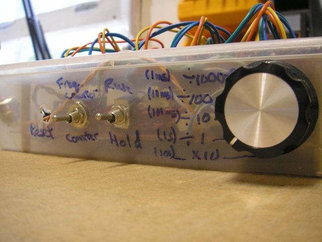
The frequency counter can have integration periods of anywhere between 1 ms to 10 s. The fixed time base can generate integration periods between 1 ms to 10 s in decade increments. There is also a variable time base will allows the user to continuously tune in between these frequencies as necessary. A switch is used to select between the fixed and variable time base. A rotary switch is used to select the decade of interest.
Implementation: During the integration period, pulses from the input port are being counted by the decade counters. After this period is over the contents of the counters will be copied over to the latches and thus be displayed. After being copied over to the latches, the counters themselves are cleared and the count starts accumulating again over a new integration period. The overflow light and counter and latch contents can be cleared by pressing the reset button. The control circuit will reset the counter and enable the latches in the correct sequency as necessary. In the even of data hold being activated, the control circuit will reset the counters in the same sequence as before, but the latches will be set to retain data until data hold is disabled.
There are two time bases in the frequency counter; a fixed and a variable. The fixed time base has a period of 1 ms. Both are fed to subsequent divide by 10 counters to achieve slower integration periods up to 10 s. These controls allow the frequency counter to continuously cover integration periods between 1 ms to 10s.
To facilitate changes, the circuit was first built on bread boards. Here is a picture of the design in action. During the excitement, I forgot to take pictures of the time base and control circuit. Here is the circuit with a 1 kHz signal being fed in.
Final build
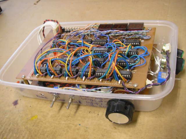
After finding the obvious bugs, I figured it was time to put some solder down and make this a permenant part of my lab bench. I constructed the display, drivers, counters and latches on one board and the time base, control generator and power supply on the other. Here are some pictures.
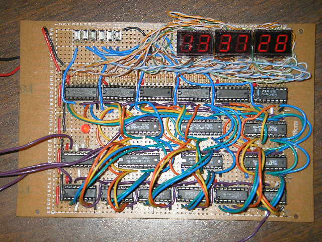
Here are the display, drivers, counters and latches.
And this is what it looks like on the bottom.
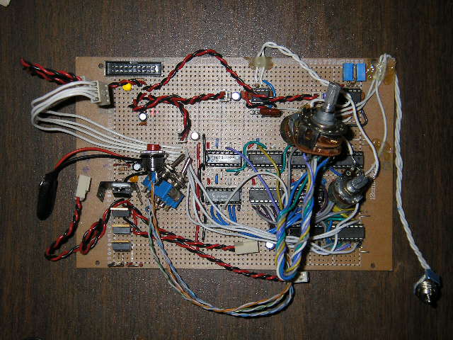
Here are the time base, control generator and power suply.
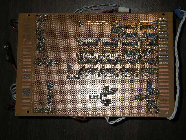
And this is what it looks like on the bottom.
Here is my weak attempt in getting it to display 1337.
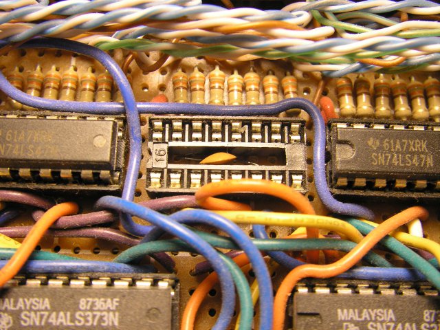
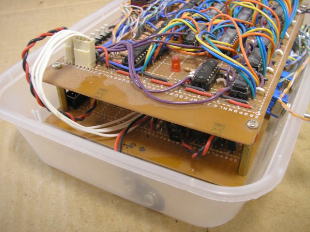
You might have noticed a large number of capacitors in the schematic, but none are seen in the photos. I promise, I am not trying to trick you, they are there, just hidden in the IC sockets, beneath the IC. I've removed an IC to expose the capacitor underneath.
The project is not complete until it has its enclosure. Being super tight on cash, I decided to use my lunch container. A few holes later, this is what it looks like (don't laugh).
View from the front with the exquisite panel work. The reset button isn't there because there was no way of installing it after the soldering was complete and I still wanted to keep the project disassemblable.
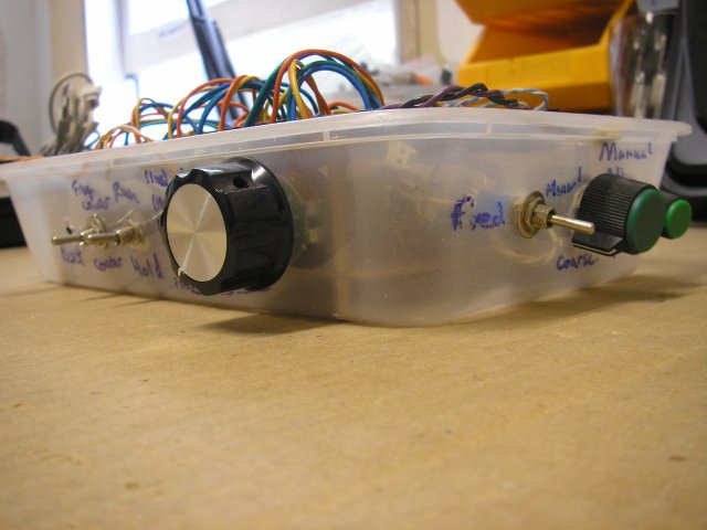
Isometric view showing the variable time base tuning knobs (coarse and fine adjust).
The boards are stacked on top of each other. The only wires coming from the bottom board to the top board are the counter and latch control signals and the power source.
Conclusion
The time bases on this device are increadibly unstable. This is because at the time, I did not know how crystal oscillators worked and did not design them into the project. Within a minute of power up, the display could fluctuate by 10%. If I were to do this project again, I would definitely design a better time base. Also, a robust analog front end would be nice. There are prescalar chips on the market these days. Throw in an FPGA and you can make a frequency counter capable of up to a few GHz. Oh, while we are at it, why don't we throw in a GPIB interface? USB? Rubidium standard? Even better, how about a GPS locked PLL? Oh boy, scope creep is ever so present.
Considering that this was built with the limited knowledge that I had at the time (and a constant tooth ache), I think it is a pretty good accomplishment. However, there is a lot more room for improvement before I would recommend it to other people.
This page was last revised on an unknown date.
![]()
