DC Motor Controller and Tachometer
Project started on 2006-04-12
Project completed on 2006-05-06
This project consists of 2 components:
- Voltage controlled motor controller
- Controlling the speed of a motor is very important in many situations especially in robotics. There are many techniques of controlling the speed of motors, each with their advantages and disadvantages. This document will show you how to build a motor controller which controls the speed of a motor by varying the input voltage.
- Electrical speed detector
- Along the same lines, it is useful in many situations to know the exact speed of the motor (in rotations per second for example). By knowing the exact speed of the motor, we can then adjust the motor's speed to exactly what we want. Once again, there are many ways to do this, the method shown in this document is purely electrical and requires no additional sensors.
Background
Motors vary in sizes, shapes and functionality. There are 3 types of motors that I know of (pictures not shown to scale):
- DC motor
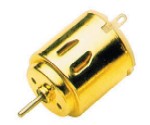
- Used for small hobby purposes to medium sized appliances (eg: handheld drill)
- Uses DC voltage source (eg: battery)
- Easy to control
- Stepper motor
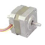
- Used for very precise movements (eg: moving an inkjet printer head)
- Are "weak"
- Need special signals to control
- AC motor
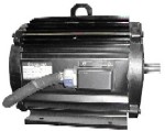
- Used for heavy duty machines and industrial purposes (eg: washing machine)
- Can be very "powerful"
- Uses a AC voltage source (eg: power outlet)
From the outside, the 3 look almost identical. They all have a rotating shaft running through the centre. For our purposes, we will be designing our components for DC motors only. DC motors are commonly used in hobby situations and robotics. They are cheap and robust and easy to use.
Quick Description of a DC Motor's Construction
DC motor are made by wrapping coils of wire around a post. These windings are placed inside a magnetic field (created by permenant magnets or electromagnets). When a voltage is applied to the windings, a current will go through the coil, which will create another magnetic field. The two magnetic fields may attact each other (like two opposite poles of magnets) or repell each other (like two similar poles of magnets). This will cause the the windings to move and rotate the central shaft of the motor. After making a half a rotation, the current going through the windings will go in reverse (due to a switch known as the commutator ring) and the motor will continue spinning. Far better descriptions can be found here:
- General article: http://en.wikipedia.org/wiki/Electric_motor
- For people interested in the principles (watch the arrows of all 3 colours carefully!): http://www.walter-fendt.de/ph11e/electricmotor.htm
- For people interested in the physics: http://hyperphysics.phy-astr.gsu.edu/HBASE/magnetic/motdc.html
Anyway, the 2 most important things to remember for this document are:
- DC motors have windings
- The current in the windings change every rotation
Motor Speed Controller
The purpose of the speed controller is to vary the speed of the motor. The name "speed controller" is somewhat of a misnomer. We can tell the motor to spin faster or slower, but we cannot predict the speed of the motor. On top of that, depending on the load that the motor is driving, the motor's speed will be effected as well. In summary, the purpose of the speed controller is to have some control over the motors speed, but we cannot tell exactly how fast the motor is spinning.
The design of this motor speed controller is very simple:
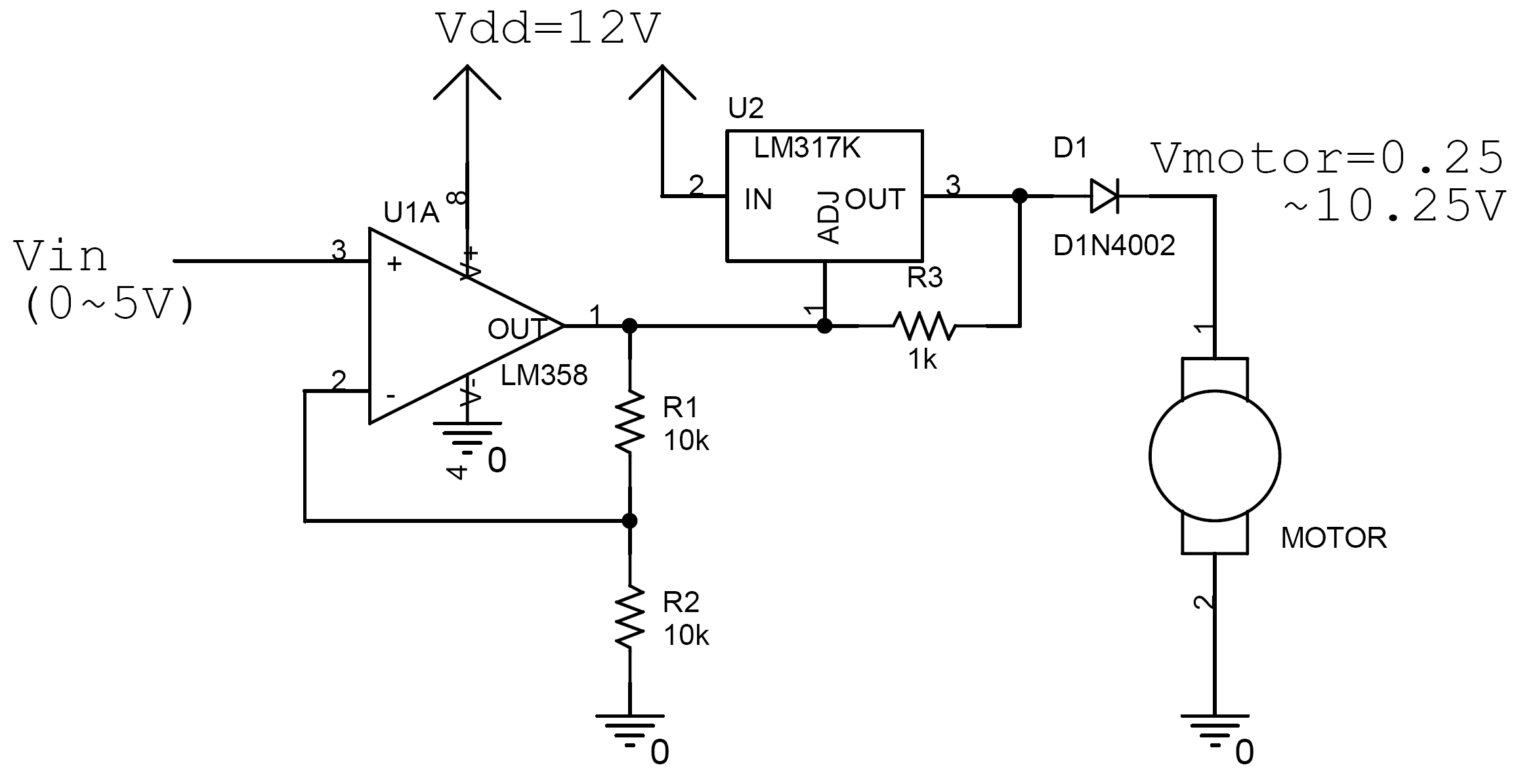
Click on image for higher resolution schematic
The principle of this speed controller is simple. The speed of the motor changes because the voltage applied to the motor changes.
Vin can be any signal voltage. If you are controlling this motor through a digital interface, you may want to use an R-2R ladder DAC. If you want manual control, you can use a potentiometer as a voltage divider.
The op-amp (U1A) is a single supply opamp, which means that it can function without a negative power supply. In most battery powered situations (like on a robot), it is not practical to have dual power supplies (positive and negative) which most op-amps require. The LM358 is a good single supply op-amp. If you can't find any LM358's, use LM158's or LM258's. They are similar enough that the circuit should still work the same. The op-amp is in the non-inverting configuration:
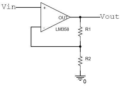
Op-amp in the non-inverting configuration
When an op-amp is wired in the maner above, we can predict the output:

Simply choose values of R1 and R2 in the range of kΩ's and make sure the output voltage stays below the supply voltage (12V in this case) by at least 1V.
The LM317 (U2) is a voltage regulator. The op-amp alone is not strong enough to drive a motor. The voltage regulator by itself is only capable of producing a constant 1.25V. By using a voltage regulator in conjunction with the op-amp, we can control the voltage (thanks to the op-amp) while having enough power (thanks to the voltage regulator) to drive a motor. The voltage regulator works by keeping Vout = Vadj + 1.25V. So by changing Vadj (see schematic), we are esentially changing Vout of the voltage regulator.
D1 is a rectifier diode. The 1N4002 was choosen in this case, but any rectifier diode would do. Most rectifier diodes have a 1V drop across them when forward biased. The purpose of the diode is to protect the electronics from the harsh environment in which the motor is operating in. The motor is built with wound coils which act as inductors. When the commutator switches, the coils act as inductors and create hugevoltage spikes which may damage the electronic circuits and pollute the power supply. By placing the diode in that position, these voltage spikes will not reach the voltage regulator and beyond.
So, for our case,

As you can see, you can choose the values of R1 and R2 to suite your situation.
I have tested this motor with a 12V power supply and 5V power supply for the digital electronics controlling Vin. A 24V hobby motor ran fine on the setup and stalled when the output voltage was around 4V. The voltage regulator did not dissipitate enough energy to become hot, even when the motor was diliberately stalled at maximum power (don't try! It could damage your components!). This was likely due to the high DC resistance of the motor's windings.
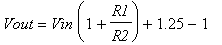
This method is not the most efficient way to control the speed of a motor. As one can see from the following diagrams, significant amount of energy is lost to the controller at low speeds.
A far more efficient method of controlling motor speeds is through pulse width modulation (PWM), however, due to the discontinuous nature of the power supply voltage, it would not work with the speed detection component descibed below.
Power transfer characteristics (assuming motor's impedence is 40Ω)
Another shortfall of this controller is its lack of ability for bidirectional motor control. In many cases, motors must have the capability of spinning both in the forward direction as well as in reverse. Conventional methods of accomplishing this involve using an H bridge. I have not incorporated an H bridge into this design, but its probably not hard to do so.
Go and look up PWM and H bridges on your favourite search engine if you're interested in learning more about motor control.
Motor Speed Detector
When a motor spins, the commutator acts like a switch, forcing the motor to perpetually realign its magnetic dipoles. Because a motor is built with coils, it acts as an inductor. When the commutator switches, the voltage drop across these inductors is forced to change. This abrupt change causes the inductor to oscillate and generate other disturbances. As mentioned above, these disturbances can cause problems with delicate electronic circuits. However, in the motor speed detector, we are use this phenomenon to our advantage to detect the motor's speed.
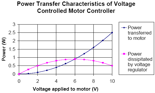
The voltage at the positive terminal of the motor (Vmotor) fluxuates very subtly (0.25Vp-p) due to the motor's rotation. This can be measured on an AC coupled oscilloscope. The DC component of this signal is of course, the applied voltage determined by the speed controller's design equation.
Subtle variations in Vmotor
The speed detector circuit converts this noisy signal into a clean digial signal which can then be easily read and processed. To do so, we need to:
- Filter out the high frequency noise (using a low pass filter)
- Filter out the low frequency DC bias (using a high pass filter)
- Convert the analog signal into a digital signal (using a Schmitt tigger)
These 3 steps were done in a sequence of cascaded RC filters:
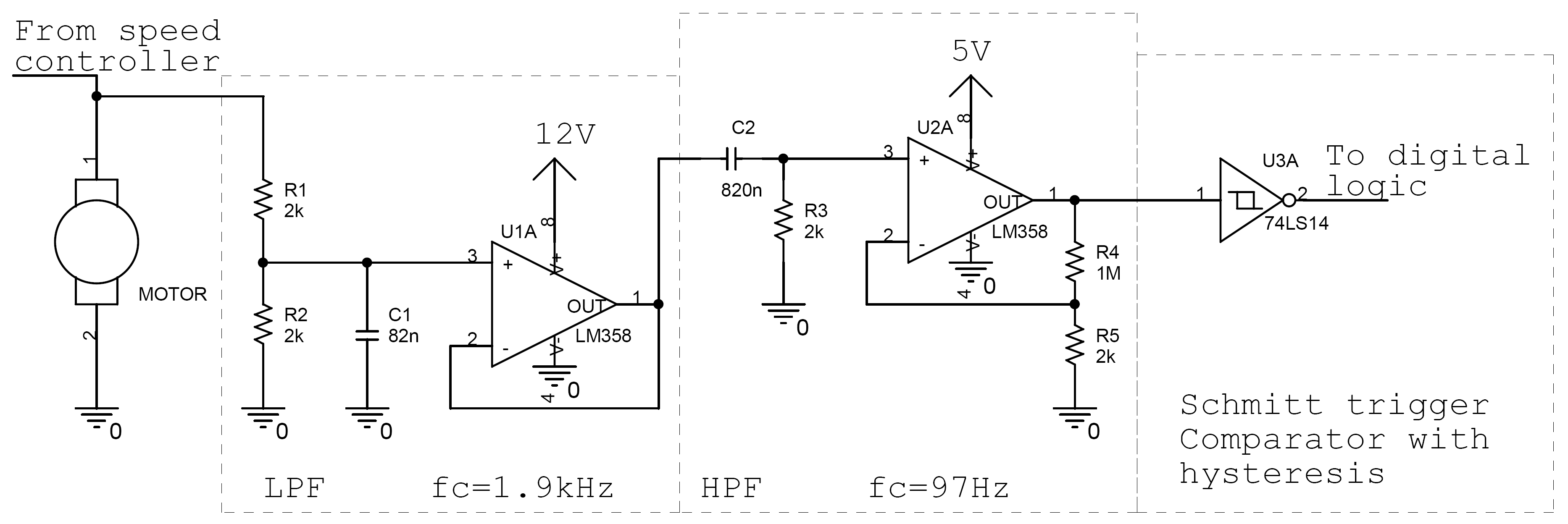
Click on image for higher resolution schematic
The resulting frequency response from the circuit above is:
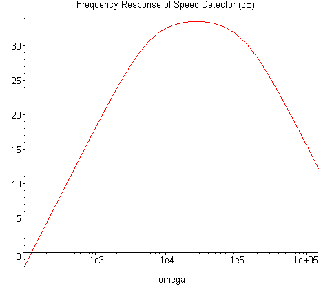
Frequency response of the circuit above
Essentially, the circuit filters out the noise and amplifies the frequencies in which the motor may be spinning at. The supply voltages for the op-amps are very important. The first op-amp (U1) is powered with 12V. This allows it to freely buffer signals around 6V without clipping. The second op-amp (U2) is powered with 5V. This ensures that the output voltage won't exceed 5V and damage the Schmitt trigger. Inevitably, the signal is clipped due to the large amplification and small power supply. However, did not become a problem, as I later found out in testing.
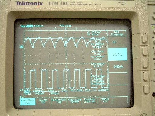
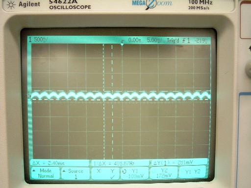
Channel 1: Input from motor with noise filtered out
Channel 2: Output of Schmitt trigger
This circuit was tested with varying supply voltages. The detection circuit successfully picked up rotational speeds all of them. Even when the motor was not powered, but hand spun, the circuit picked up the rotation as well.
It should be noted that most DC motors contain more than 2 arms to avoid deadlock on start up, most small hobby motors have 3 arms. Hence, the number of pulses per revolution is the same as the number of arms a motor contains internally. You can find out how many arms your motor has by either taking it apart or counting the number of pulses and divide it by the number of revolutions made over a period of time.
This speed detection circuit is better suited in many situations. Other methods of detecting motor speed include:
- Using a reed switch
- Using a magnetic reluctance sensor
- Using a hall effect sensor
- Using a light source and optical sensors
- Generate an EMF and sampling that
With the options above, they all require external hardware to be built and physically attached to the motor. In many situations where space is tight, they may not be good ideas. Furthuremore, they all require additional circuitry which is not any simpler than the speed detector mentioned above.
Construction
These circuits worked fine on breadboard. You should solder it onto a perf board or PCB to minimize noise, but noise is definitely not an issue for this circuit.
To minimize noise from the motor from effecting other delicate signals in your project, you should try to:
- Keep your motor drive and detection circuit physically far apart from your sensitive signals
- Decouple your power supply with capacitors around your sensitive circuits
- Use buffers or transeivers between your motor driver and digital logic
- Braid or twist the wires that power your motor (minimizes the area and magnetic flux)
The bill of materials is as follows:
| Item | Quantity | Unit Cost |
|---|---|---|
| LM358 | 1 | 0.80 |
| LM317 | 1 | 0.75 |
| 10kΩ 1/4W resistor 5% | 2 | 0.01 |
| 1kΩ 1/4W resistor 5% | 1 | 0.01 |
| 1N4002 | 1 | 0.10 |
| Item | Quantity | Unit Cost |
|---|---|---|
| LM358 | 2 | 0.80 |
| 74LS14 | 1 | 0.65 |
| 820nF non-polarized capacitor | 1 | 0.75 |
| 82nF non-polarized capacitor | 1 | 0.15 |
| 2kΩ 1/4W resistor 5% | 4 | 0.01 |
| 1MΩ 1/4W resistor 5% | 1 | 0.01 |
Cost for the speed controller is around $2 and the cost for the speed detector is around $4. Sure beats having to buy pricy opto sensors or other detectors.
Future Plans
Some ideas to improve these two components:
- Add bidirectional capability to the speed controller
- Create a realtime feedback system using an FPGA to provide constant speed under varying loads
Please contact me if you have other cool ideas.
This page was last revised on an unknown date.
![]()
